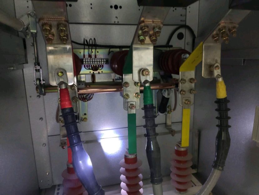
Every electrical power distribution system relies on protective devices to ensure the safety of equipment and prevent potential hazards such as fires or user injuries. Among these protective devices are earthing switches, vital components within switchgear systems that play a crucial role in safeguarding electrical equipment.
What is an Earthing Switch?
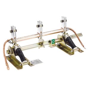
An earthing switch, also referred to as a grounding switch, is a protective mechanical switching device integrated into switchgear components such as circuit breakers and isolators. These terms, “earthing switch” and “grounding switch,” are often used interchangeably. The primary function of an earthing switch is to ground a portion of the busbar when abnormal conditions, such as short circuits, occur. It remains inactive during normal circuit operation but is activated in response to abnormal events, making it an essential component in electrical installations.
Key Functions:
-
Circuit Grounding:
Earthing switches are designed to ground the remaining charge in a power line after it has been disconnected from its power source. Residual charges frequently persist in circuits even after being opened by circuit breakers and isolators, and earthing switches effectively discharge these charges.
-
Safety Mechanism:
Equipped with a snap-action closing mechanism, earthing switches protect technicians and personnel during abnormal current situations. They are robustly built to withstand short circuits and can also be motorized for automated operation. Notable examples include high-voltage earthing switches and high-speed grounding switches.
-
Substation Protection:
In substations, earthing switches play a critical role by creating short circuits when necessary to protect other electrical devices from potential damage. They serve as essential protective elements during the maintenance and overhaul of high-voltage electrical equipment.
Device Varieties:
-
Integration with RMU:
Earthing switches are often integrated into Ring Main Units (RMU) alongside circuit breakers and isolators. Proper sequencing of these devices during circuit opening or maintenance is imperative to prevent equipment damage and ensure safety.
-
Combined Earthing and Isolating Switches:
In certain configurations, earthing switches and isolating switches are consolidated into a single device. In addition to the primary contact, isolating switches within these devices feature an integrated earthing switch for grounding one end once the isolator is opened. Mechanical interlocks are commonly employed to prevent simultaneous operation of the earthing and isolating switches.
-
Open and Closed Types:
Grounding switches are categorized into open and closed types. Open-type grounding switches expose their conduction systems to the atmosphere, much like disconnectors. In contrast, the conduction system of closed-type grounding switches is enclosed within insulating or dielectric mediums, such as SF6 or oil.
-
Short-Circuit Handling:
Earthing switches are designed to close short-circuit currents and possess specific short-circuit making capacity, along with dynamic and thermal stability. They lack arc-quenching mechanisms, as their primary role does not involve interrupting load currents but ensuring safe circuit grounding.
-
Structures:
Earthing switches come in various structural configurations, including single-pole, double-pole, and three-pole arrangements. Single-pole switches are used in neutral point grounding systems, while double-pole and three-pole switches are suited for neutral point ungrounded systems, sharing a common operating mechanism for coordinated functionality.
Earthing Switch in Low-Voltage Systems:
In low-voltage systems serving a wide range of end-users, earthing switches are primarily designed with customer safety in mind. They work in conjunction with other switchgear protection components, such as load break switches and residual current devices, to prevent users from coming into contact with metallic objects exceeding a safe voltage threshold (typically set at 50 volts). These safety measures ensure protection against electric shocks and guarantee user safety in publicly accessible networks.
Earthing Switch in High-Voltage Systems:
In high-voltage substations, safety concerns take a back seat compared to supply reliability, protection reliability, and equipment impact during short circuits. The choice of earthing system mainly affects the amplitude of phase-to-ground short circuits, which are the most common. The focus here is on ensuring supply continuity and minimizing equipment damage.
Applications of Earthing Switch:
Earthing switches serve several critical functions:
- Providing a ground line for underground or delta-connected systems.
- Allowing phase-to-phase load connections.
- Ensuring a low-impedance link to ground, maintaining system neutrality.
- Limiting transient overvoltage magnitude during re-striking ground faults.
- Providing a ground fault current source during line-to-ground faults.
- Grounding electrical devices to meet protection requirements.
Function of Earthing Switch: The primary function of an earthing switch is to protect technicians, switchgear, and electrical equipment from inadvertent operations. It can reliably close against short-circuit currents and is connected to circuit breakers. When circuit breakers are disconnected, earthing switches automatically ground the adjacent busbar, ensuring the safety of maintenance personnel and users.

Types of Earthing Switch:
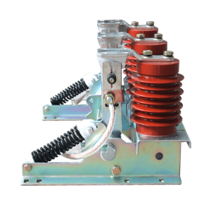
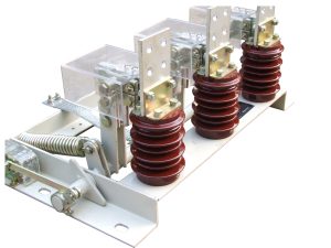
- Indoor High Voltage Grounding Switch: Suitable for indoor 3-12kV three-phase AC power systems, used in conjunction with various types of high-voltage switch cabinets. It can also serve as grounding for high-voltage electrical equipment maintenance.
- Indoor High Voltage Electric Grounding Switch: Equipped with a motor, driving device, and electric air control device, primarily designed for indoor use.
- FES Fast Earthing Switch: Designed to close short-circuit currents and open/close induced currents, this switch is crucial for rapid fault clearing during maintenance. It is often equipped with an electric spring mechanism.
Design of High-Speed Grounding Switch: The High-Speed Grounding Switch (HSGS) is typically installed at the outlet end of Gas Insulated Switchgear (GIS) and operates using a spring mechanism. It serves as a secondary safety measure to safeguard the power system in case of accidental energization and closure. HSGS ensures that specified short-circuit making capacity is maintained.
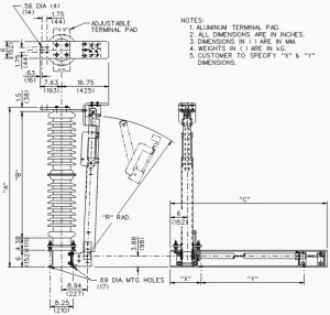
Difference between Earthing Switch and High-Speed Grounding Switch:
- Earthing switches are typically located adjacent to disconnectors and serve to ground circuit sections during maintenance. In contrast, high-speed grounding switches are positioned on the line side of outgoing circuit disconnectors and have two key functions: rapid arc extinguishing and system grounding.
- High-speed grounding switches are crucial for closing the parallel overhead lines generating inductive currents, while earthing switches do not perform this function.
Relationship between Circuit Breaker and High-Speed Grounding Switch: High-speed grounding switches are often used in conjunction with circuit breakers to achieve rapid arc extinguishing and reclosing during single-phase faults. These switches help reduce the submerged supply current, enhancing arc extinguishing capabilities.
Conclusion: Earthing switches are fundamental protective devices in electrical systems, ensuring the safety of technicians, users, and equipment. They are indispensable components within switchgear systems, contributing to the efficient and secure operation of power distribution networks. For reliable protective electrical components, including earthing switches, contact reputable manufacturers such as green energy electrical to enhance safety and prevent accidents in your electrical installations.

